Almost every install that never connects is a fit problem. Every PULSE is tested before it ships.
Along the right edge of the main board, next to the two black buttons, is a row of five holes: VCC, DIO, DCK, reset and GND. The PULSE has spring pins for only three of them: DIO, DCK and GND. The VCC hole at the top and the reset hole must stay empty.
The common mistake: the top pin looks as if it belongs in the top hole, so the PULSE ends up one hole too far up, with a pin in VCC. It looks connected, but it isn’t. The opening in the middle of the PULSE is made to fit right over the silver on/off switch in the middle of the main board. If it’s even slightly off, the pins miss.
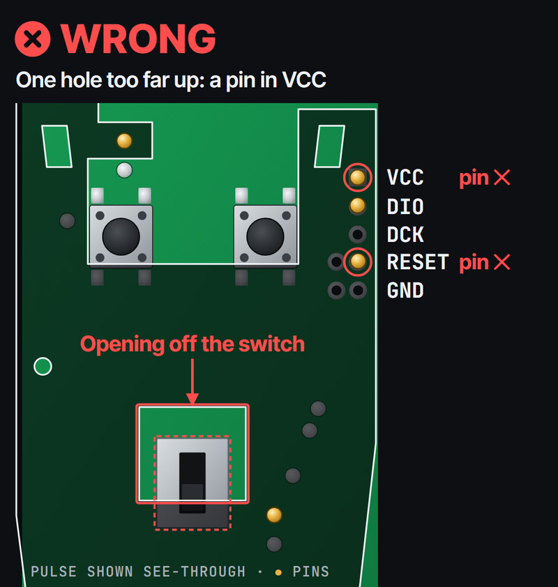
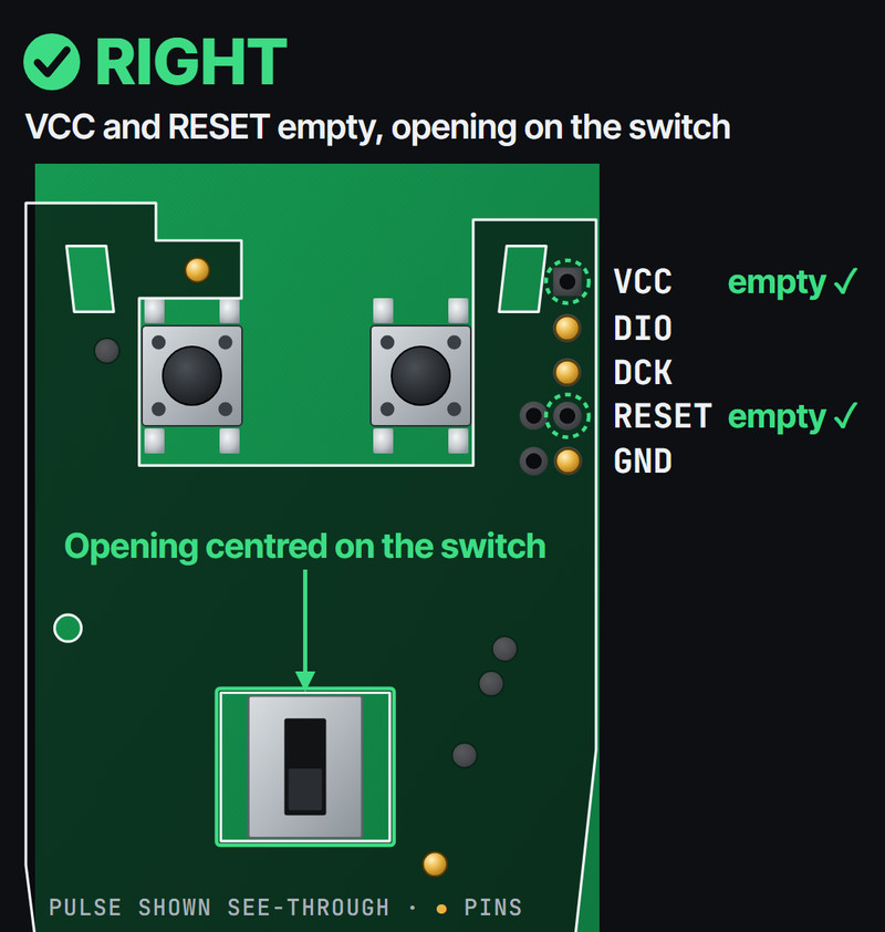
Don’t place it by hand. Let the cover line it up for you:
- Clip the PULSE into the front cover (install guide step 8).
- Close the cover straight down onto the handle (step 9).
- Squeeze the seam firmly all the way round (step 10).
Then do the power check before you try another install.
Still not connecting after that? See An install failed, or send us a report with a photo of the main board.